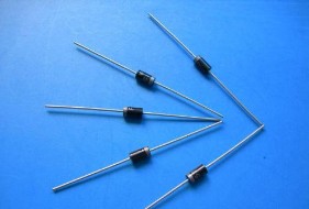
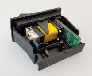
This paper mainly introduces the rectifier diode, and focuses on the ac through the rectifier diode method for detailed analysis.
A semiconductor device that converts alternating current into direct current.Usually it contains a PN junction, with positive and negative terminals.The most important characteristic of a diode is its one - way conductivity.In a circuit, current can only flow in from the positive pole of a diode and out from the negative pole.
An overview of the
A semiconductor device that converts alternating to direct current (dc).The most important characteristic of a diode is its one - way conductivity.In a circuit, current can only flow in from the positive pole of a diode and out from the negative pole.Usually it contains a PN junction, with positive and negative terminals.Its structure is shown in the figure.The charge carriers in the P region are holes and the charge carriers in the N region are electrons.When the applied voltage makes the voltage in the P region positive relative to the N region, the potential barrier will be reduced, and a storage carrier will be generated near the two sides of the potential barrier, which can pass through a large current and has a low voltage drop (the typical value is 0.7v), which is called the positive conduction state.If the opposite voltage is added, the barrier can be increased to withstand high reverse voltage and flow through a small reverse current (called reverse leakage current), which is called reverse blocking state.Rectifier diode has obvious unidirectional conductivity.Rectifier diodes can be made of semiconductor materials such as germanium or silicon.The silicon rectifier diode has high breakdown voltage, small reverse leakage current and good high temperature performance.High voltage and high power rectifier diodes are usually made of high purity monocrystalline silicon.The junction area of this kind of device is large, and can pass a large current (up to thousands of amperes), but the working frequency is not high, generally in the tens of KHZ.Rectifier diodes are mainly used in a variety of low-frequency half-wave rectifier circuits.

Commonly used parameters
(1) maximum average rectifier current IF: refers to the maximum forward average current allowed to pass through the diode during long-term operation.The current is determined by the junction area of the PN junction and the cooling condition.Note that the average current through the diode should not be greater than this value, and to meet the cooling conditions.For example, IF of 1N4000 series diode is 1A.
(2) highest reverse working voltage VR: refers to the maximum reverse voltage allowed to be applied at both ends of the diode.If the value is larger than this value, the reverse current (IR) will increase sharply, and the unidirectional conductivity of diode will be destroyed, thus causing the reverse breakdown.Half of the reverse breakdown voltage (VB) is usually taken as (VR).For example, VR of 1N4001 is 50V, 1n4002-1n4006 is 100V, 200V, 400V, 600V and 800V respectively, and VR of 1N4007 is 1000V
(3) maximum reverse current IR: it is the reverse current allowed to flow through the diode at the highest reverse operating voltage. This parameter reflects the unidirectional conductivity of the diode.Therefore, the smaller the current value, the better the quality of the diode.
(4) breakdown voltage VB: refers to the voltage value at the sharp bending point of the diode reverse volt-ampere characteristic curve.When the reverse is a soft characteristic, it refers to the voltage value under the condition of given reverse leakage current.
(5) highest working frequency FM: it is the highest working frequency of diode under normal conditions.Mainly determined by the junction capacitance and diffusion capacitance of PN junction, if the working frequency exceeds FM, the unidirectional conductivity of diode will not be well reflected.For example, the 1N4000 series diode has an FM of 3kHz.Quick recovery diodes are also used for rectification of high frequency alternating current, such as switching power supplies.
(6) reverse recovery time TRR: refers to the reverse recovery time under the specified load, forward current and maximum reverse transient voltage.
(7) zero-bias capacitor CO: refers to the sum of the capacity of the diffusion capacitor and the junction capacitor when the voltage at both ends of the diode is zero.It is worth noting that due to the limitation of manufacturing process, the parameters of even the same type of diode are very discrete.Is often a range of parameters in the manual, if the test conditions change, the corresponding parameters will also change, such as the measured 1 at 25 ° C n5200 series silicone sealants rectifier diode IR less than 10 ua, whereas at 100 ° C IR to less than 500 ua.
The voltage reduction problem of alternating current passing through a rectifier diode
The rated output current of the rectifier bridge varies with the type of diode.
For example, KBPC1510 voltage 1500V, current 10A
KBPC1015 voltage 1000V, current 15A...
12V ac with rectifier diode rectifier into 12V dc: rectifier diode parameters: withstand voltage of 50 v above, the current is greater than the load current, can be.
Such as IN4001 -- -- -- -- -- IN4007;Voltage 50---- 700 volts, current 1 ampere.
IN5401-- IN5408: voltage: 50---- --800 volts, current: 3 amperes
How to convert alternating current to direct current
I. circuit principle
The basic circuit of capacitive step-down simple power supply is shown in figure 1. C1 is a step-down capacitor, VD2 is a half-wave rectifier diode, VD1 provides a discharge circuit for C1 when the power supply is in the negative half cycle, VD3 is a voltage stabilizing diode, and R1 is the charge discharge resistance of C1 after turning off the power supply.The circuit shown in figure 2 is often used in practical applications.The bridge rectifier circuit shown in figure 3 can be used when a large current needs to be supplied to the load.
After rectification, the unstabilized dc voltage is generally higher than 30 v, and will fluctuate greatly with the change of load current. This is because the internal resistance of such power supply is very large, so it is not suitable for the application of high-current power supply.
Ii. Device selection
1. In circuit design, the exact value of the load current should be measured first, and then the capacity of the step-down capacitor should be selected by referring to the example.Because the current Io provided to the load by the step-down capacitor C1 is actually the charging and discharging current Ic flowing through C1.The larger the capacity of C1, the smaller the capacitive reactance Xc, and the larger the charge and discharge current flowing through C1.When the load current Io is less than the charge and discharge current C1, the excess current will flow through the regulated voltage tube. If the maximum allowable current Idmax of the regulated voltage tube is less than ic-io, the regulated voltage tube will easily burn down.
2. In order to ensure the reliable operation of C1, its voltage withstand selection should be greater than twice the power supply voltage.
3. The discharge resistor R1 must be selected to discharge the charge on C1 within the required time.
Iii. Design examples
For example, calculate the load current
In figure 2, given C1 is 0.33 F and ac input is 220V/50Hz, the maximum current that the circuit can supply to the load is calculated.The capacitance reactance Xc of C1 in the circuit is:
Xc=1 / (2*3.14*50*0.33*10-6) = 9.65k
The charging current (Ic) flowing through capacitor C1 is:
Ic = U/Xc = 220/9.65 = 22mA.
Normally, the relationship between the capacity C of step-down capacitor C1 and the load current Io can be approximately considered as: C=14.5*I, where the capacity unit of C is F and the unit of Io is A.
Example two, according to step-down voltage element selection
As shown in figure 2: if 220V ac is reduced to 10V dc using a capacitive step-down circuit, how should the various component parameters be selected?(how big is the resistance, capacitance and diode)
C1 is selected according to the required current size, providing a maximum current of 68mA per 1u capacitor.
R1 is the discharge resistance, to prevent electric shock injury on the capacitor after power off, generally about 820k-1m.
Voltage regulator diode VD1 with 10V/1W.
VD2 is a rectifier diode, using 1N4001~4007 can be.
C2 is the filter capacitance, 100u is enough, because this circuit will not have a large current
Four, application attention
Note the following when using capacitor voltage reduction:
The appropriate capacitance should be chosen according to the current of the load and the working frequency of alternating current, not according to the voltage and power of the load.
Current limiting capacitors must be non-polar capacitors, absolutely not electrolytic capacitors.And the capacitance of the voltage must be more than 400V.The most ideal capacitance is iron - clad oil - immersed capacitance.
Capacitance buck cannot be used in high power conditions because it is unsafe.
Capacitance buck is not suitable for dynamic load conditions.
Similarly, capacitive voltage reduction is not suitable for capacitance and inductive load.
When dc operation is required, half-wave rectification shall be adopted as far as possible.Bridge rectifier is not recommended.And it has to be under constant load.
Capacitor step-down power supply is a kind of non-isolated power supply. Special attention should be paid to isolation in application to prevent electric shock.
conclusion
The relevant introduction of rectifier diode is here, if there is a deficiency welcome correction.

 英语
英语  中文
中文  德语
德语  韩语
韩语  日语
日语  波斯语
波斯语  葡萄牙语
葡萄牙语  俄语
俄语  西班牙语
西班牙语 


