Production process supervision and control to use a variety of automated instruments, facing more and more severe environment, in order to solve the interference, the instrument connected to the isolation terminal must meet two basic requirements: the first is to solve various equipment, instrument "ground" difference, namely the signal reference point potential difference;The second is electromagnetic compatibility.
Electrical isolation and electromagnetic compatibility -- basic requirements for the anti-interference of isolated terminals
1. Two principles of electrical isolation
Signals of different equipment and instruments with different common modes are input into DCS, PLC and other control systems. If they are directly connected without processing, they may cause interference due to "different common modes" of signals.The so-called "common mode difference" mainly refers to the reference point potential difference between signals.The input/output electrical isolation characteristics of the isolation terminal enable it to suppress the common mode signal with a strong ability, it can be with the common mode of the signal into a signal without common mode through the isolated output.Therefore, the problem can be solved by inserting isolated terminals between each external signal and the acquisition board of the control system.
In another case, a signal is required to transmit both to the display instrument and to a device such as a frequency converter.In addition to input and output isolation, the two outputs are required to be isolated from each other to eliminate device interference.An isolated signal allocator can be used, as shown in WS15242 in figure 1.
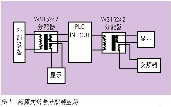
To sum up, two principles should be followed to solve the interference of reference point potential difference type.First: external equipment signal and central processing system (such as PLC, DCS) between the electrical isolation.
Second: external signals (whether received or emitted from an interface to the system) must be electrically isolated from each other.By following these two principles, the system installation can completely overcome the interference introduced by the reference point potential difference.
Most of the isolation terminals are external working power supply, generally DC 24V or AC 220V.This power supply must be electrically isolated from the input/output departments when supplying power to the input/output departments.This kind of product which is isolated between input/output/external working power supply is called fully isolated terminal.Theoretically, this mode of power supply can be supplied by a single power source regardless of the number of isolated terminals.Such a connection conforms to both principles.

2. Electromagnetic compatibility
According to the international electrotechnical commission (IEC), electromagnetic compatibility (EMC) is a function of electronic equipment.Electronic devices can perform their functions in an electromagnetic environment without intolerable interference.
According to the EMC scale, the isolated terminals are required to be able to work normally in the electromagnetic interference environment, and inorganic energy can reduce or fault, so as to ensure the accuracy, stability and other parameter changes within the designated range.At the same time, the electromagnetic intensity generated by the isolated terminal as the source of electromagnetic harassment should also be controlled within the designated range to weaken its electromagnetic pollution to the environment.

In 1997 and 1999, the international electrotechnical commission (IEC) issued the immunity test in industrial environment and the emission scale in industrial environment as the general scale of electromagnetic compatibility.China has also issued its equivalent documents: GB/ t17799.2-2003 and gb17799.4-2001.The eu CE also has the same scale, standardizing products entering the eu market.These files are also the size to which the isolation terminal should be scaled.
It is necessary to have three basic elements to form electromagnetic interference consequences, namely, electromagnetic disturbance source, coupling channel and sensitive equipment.The task of EMC design is to weaken the disturbance source energy, block the coupling channel, and improve the equipment's ability to resist electromagnetic interference.EMC of isolated terminals should also start from design.Because it belongs to the instrument that processes signal, power is small, external transmission energy is low also.In the design, as long as a little attention to reduce the electromagnetic pollution of the product to the environment, the "emission scale in the industrial environment" requirements are relatively easy to achieve.Its design focuses on improving the ability to resist electromagnetic harassment.Figure 2 shows the variation of output signals of the two isolated terminals in the rf am electromagnetic field test to illustrate the importance of electromagnetic compatibility.
2 application selection
1. Select products according to the interface
The most common signals in industrial process control are 4 ~ 20mA and 0 ~ 10V. Physical quantities such as pressure, temperature and flow rate should be converted into 4 ~ 20mA and 0 ~ 10V signals for computer processing.Equipment that converts these physical quantities into 4 ~ 20mA and 0 ~ 10V signals is called a transmitter.Figure 3 shows the connection diagram of the isolated temperature transmitter.In the figure, Pt100 is a temperature sensor whose resistance changes to reflect the temperature changes, so the lead resistance of the connecting wire will introduce errors.Such transmitters as WS9050 and WS2050 have long line compensation function, which can eliminate the error of lead resistance and have linearization function to ensure the accuracy of conversion.
WS2050 is a type of two-wire transmitter. Its power supply and output are "in the same place" without isolation.When multiple Pt100 are transmitted to PLC via WS2050, although the output shares a 24V power supply, as long as the output is connected to the analog input board with a common reference point, this connection conforms to the two principles mentioned above in this paper.Note: the multi-way WS2050 will use their own 24V power supply when connected to different PLCS.

There is another way to isolate the transmitter. The sensor and transmitter are integrated and must be placed in the designated site.At this time, the isolated terminal is usually installed in the cabinet of the central control room.Figure 4 shows two product couplings for different interfaces.Which one to use depends on the PLC interface.
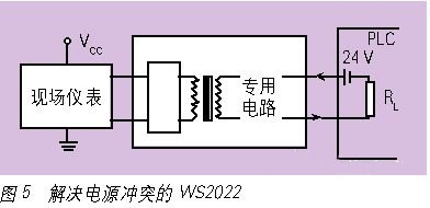
Field debugging may also lead to mismatches between the instrument and PLC interface. The sending device is a four-wire transmitter with output of 4-20ma, while the receiver's interface of 4-20ma is a two-wire circuit power supply mode (24V power supply and RL mode in figure 5). Direct connection will cause power conflicts.The solution is to use the isolation terminal to receive and isolate the 4 ~ 20mA on site, and install a special circuit in the internal output department of the isolation terminal to match the PLC power supply interface of the two-wire circuit.As shown in figure 5.This isolated terminal can also process 0 ~ 10V, 0 ~ 5A AC input voltage current signal.
Figure 3 to figure 5 shows that the selection of isolation terminal depends on whether the input port is connected to the sensor or the voltage and current signal, or is connected to the two-wire system transmitter, and then the output voltage is still the current. If the output current is 4 ~ 20mA, it is necessary to determine which of the two receiving modes of PLC in figure 4.
Generally, 4 ~ 20mA current signal isolators need external working power supply.An isolator WS1562 that does not require additional power is recommended.As shown in figure 6.The biggest feature of WS1562 is that there is no need for external power supply, and the wiring is simple, low power consumption and high reliable function. The multi-channel connection conforms to the above two principles.
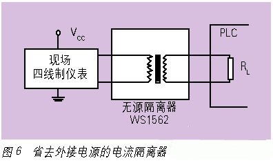
Figure 7 is the relation curve of WS1562 output load and input terminal voltage under the premise of 20mA output.VIN represents the input terminal voltage, RL represents the output load resistance and VO represents the voltage on the output load resistance.
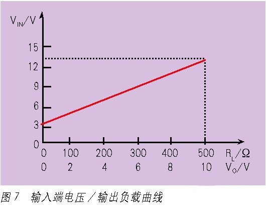
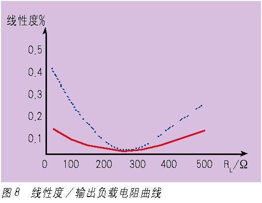
Figure 8 shows two passive isolator output load curve of linear degree, including solid lines depict the function is good, the output load resistor RL Ω changes from 0 to 500, linearity is within 0.2%.
2. Selection of main parameters
In addition to determining the function of the isolated terminal and paying attention to adapting the front and rear interfaces, there are many parameters such as accuracy, power consumption, noise, edge strength and bus communication function that need to be carefully selected by users
Accuracy is an important parameter.It has a lot of parameters associated with it.The two parameters of time drift and temperature drift indicate
The accuracy of the degree, the requirements of these two parameters as small as possible.
Another parameter that affects accuracy is noise.Because the isolation terminal generally USES DC/DC to generate isolation power supply to the internal circuit of the product, and the input signal should be first modulated into a pulse and then demodulated to the output through the isolation band (optocoupler or transformer).The cpu-core isolated terminal also has pulse signal.The frequency of these working pulses is mostly in the range of 20kHz ~ 500kHz, and its edge is steep and rich in harmonic, so it is difficult to eliminate the signal pollution.If the noise level is high, the signal collected by the data collector will have a large error, so the less peak noise and energy, the better.
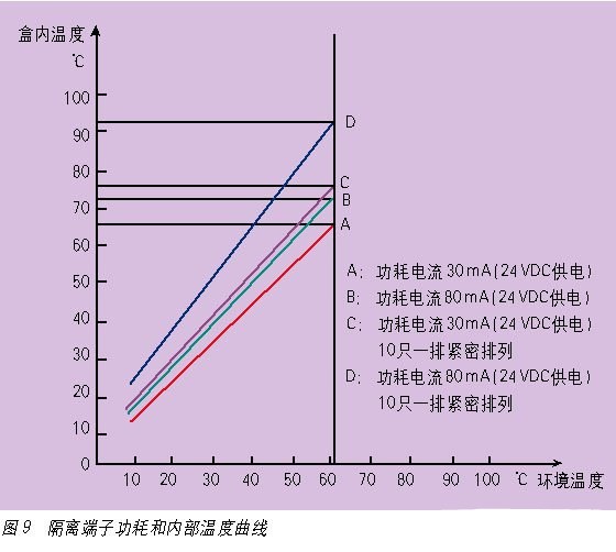
Power consumption refers to the electrical energy consumed when the isolated terminal works, which is related to the internal heat temperature of the product.FIG. 9 shows the relation curve between the internal temperature and the ambient temperature (known as the working temperature on the product imitation sheet) under the premise that two isolated terminals with different power consumption are arranged in two ways: independent placement and 10 terminals in a tight arrangement.
The D curve in FIG. 9 indicates that the internal temperature of the product is higher when the product itself consumes more power, is in a tight arrangement and the environment temperature is higher.High temperature environment for a long time will make the internal integrated circuit parameters decay, resistance value change, capacitor leakage increase, resulting in product function decline, reliability reduction, or even failure.
Isolation terminal design is becoming smaller, its purpose is to occupy less space, allowing dense installation.Intensive installation exists on the heat dissipation title, further, it is necessary to reduce the working current of the product, reduce the internal temperature of the product, which is one of the measures to improve the reliability of the product.
The isolation terminal is installed with guide rail, and the connection is connected with terminal wiring, which is installed in the cabinet.

 英语
英语  中文
中文  德语
德语  韩语
韩语  日语
日语  波斯语
波斯语  葡萄牙语
葡萄牙语  俄语
俄语  西班牙语
西班牙语 

